KPRO HARDWARE INSTALLATION GUIDE
WARNING: PROFESSIONAL INSTALLATION REQUIRED
Do not attempt to solder the ECU yourself unless you are a qualified and experienced technician. For professional assistance, please contact us. By attempting to modify the ECU, you assume full responsibility for any damage caused to the vehicle.
MODIFICATION CHECKLIST
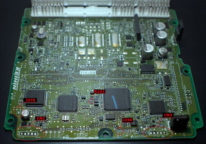
Five components must be modified on the ECU PCB to properly install the daughterboard. Prepare your workstation and ensure you locate these exact points on the board.
- CN2
- CN3
- J270
- J250
- R243
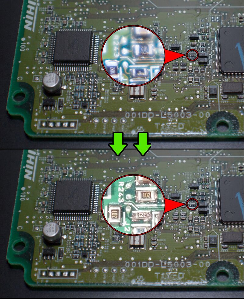
Modify R243
Install 22kΩ resistor in place of R243 jumper.
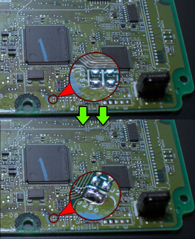
Bridge J250
Bridge J250 with solder.
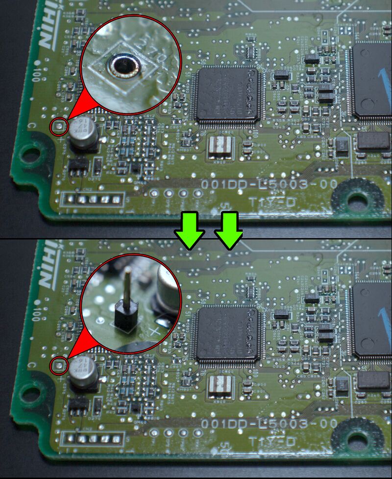
Solder J270
Solder 1-pin connector at the J270 location.
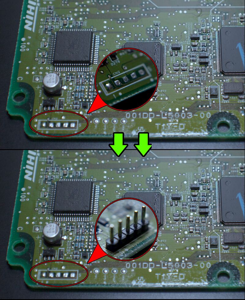
Solder CN2
Solder 5-pin connector at the CN2 location.
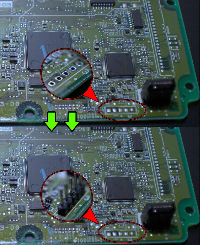
Solder CN3
Solder 5-pin connector at the CN3 location.
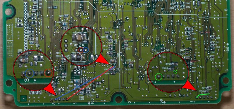
Jumper Wires
Solder 3 jumper wires between the points shown in the picture.
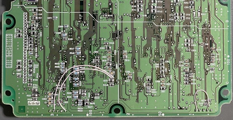
Wire Soldering Example
Example of correct wire soldering execution.
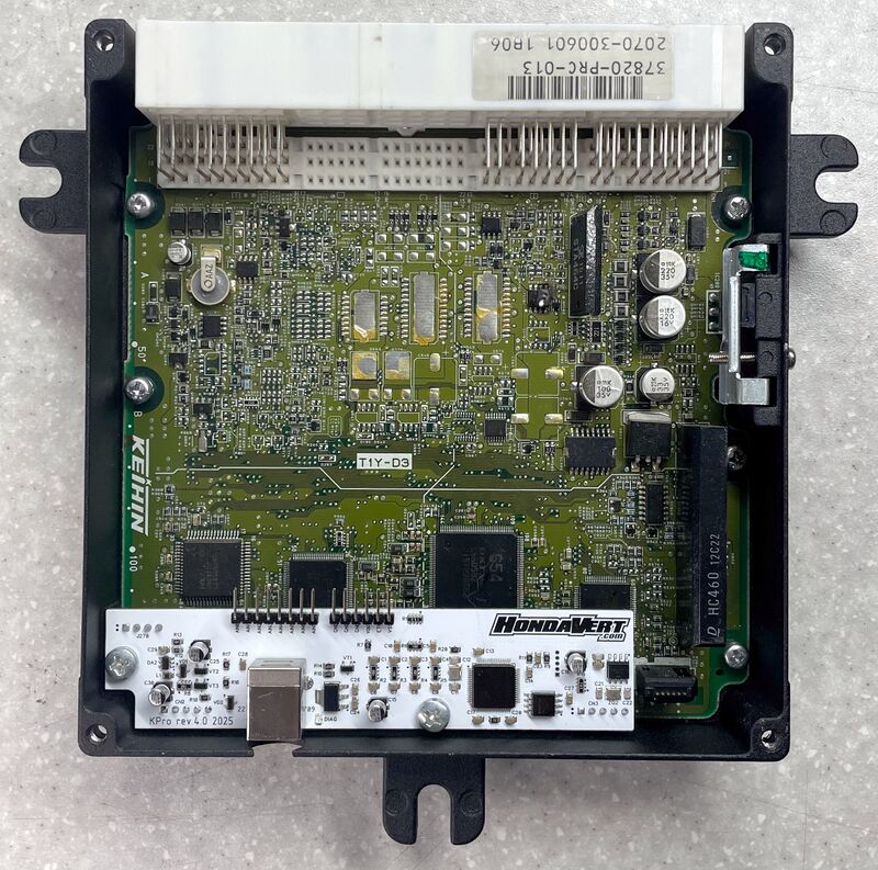
Physical Installation
Drill hole for USB. Install KPro board with supplied screws.
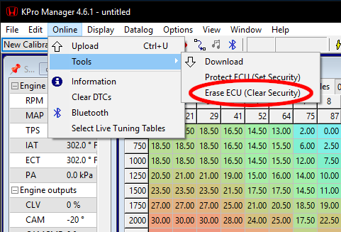
FIRST UPLOAD
Before you can successfully upload a tune to the ECU for the first time, you must clear the security settings in the KPro Manager software.